Showing posts with label Networking Tips. Show all posts

Wednesday, October 14, 2009

Conflict IP Address on the network

Have you ever encountered a network problem or error message that says "Conflict IP address in a network?" It means that there is two or more the same IP address in your network. Sometimes it is happening when your IP address was obtained manually because you might maybe forgot that you already put the first IP address in some of the computers. There is a way to avoid conflicting of IP Addresses in a network and that is manually putting of a static IP address in your computers. To solve this problem either you put the IP address automatically or recheck and put it manually again a different IP address for that particular computer.

Follow these Instructions on how to automatically or manually set a static IP Address in Network Computers.
Do one of the following: Manually
1. Right Click the Icon of "My Network Places" then go to properties.
2. Right Click the "Local Area Network Icon" then choose properties.
3. When the Local Area Network Properties appear, look and double click on the “Internet Protocol (TCP\IP)” or click the button Properties.
4. Then the Internet Protocol (TCP\IP) Properties will appear. Click "Use the Following IP Addresses".
5. Then you can now set manually an IP Addresses for that particular computer. Including your subnet mask "255.255.255.0" and the default gateway of the internet server.

Do one of the following: Automatically
1. If you want IP settings to be assigned automatically, first repeat the procedure 1, 2, and 3 above, when the Internet Protocol (TCP\IP) Properties appear, click Obtain an IP address automatically, and then click OK.

Wednesday, January 28, 2009

How to make a Network Cable


Ethernet Category 5 Cable The steps below are general Ethernet Category 5 (commonly known as Cat5) cable construction guidelines. In this example, we will be making a Category 5 cable, but the same general method will work for making any category of network cables.

Step1:
Unroll the required length of network cable and add a little extra, just in case. If a boot is to be fitted, do so before stripping away the sleeve and ensure the boot faces the correct way.
Ethernet Category 5 CableStep 2:
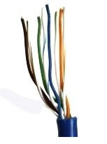
Carefully remove the outer jacket of the cable, exposing about 1 1/5 inch of the twisted pairs. Be careful when stripping the jacket as to not nick or cut the internal wiring. After removing the outer case, you will notice 8 wires twisted in 4 pairs. Each pair will have one wire of a certain color and another wire that is white with a colored stripe matching its partner (this wire is called a tracer). Sometimes a rip cord (white thread) is also present.
Ethernet Category 5 CableStep 3:
Untwist the pairs so they will lay flat between your fingers. The white piece of thread can be cut off even with the jacket and disposed. For easier handling, cut the wires so that they are 3/4" (19 mm) long from the base of the jacket.
Ethernet Category 5 CableStep 4:
Arrange the wires based on the wiring specifications you are following. There are two methods set by the TIA 568A and 568B. Which one you use will depend on what is being connected. A straight-through cable is used to connect two different-layer devices (e.g. a hub and a PC). Two like devices normally require a cross-over cable. The difference between the two is that a straight-through cable has both ends wired identically, while a cross-over cable has one end wired 568A and the other end wired 568B. For our demonstration in the following steps, we will use 568B, but the instructions can easily be adapted to 568A.

568B - Put the wires in the following order, from left to right:
White orange/ orange/ white green/ blue/ white blue/ green/ white brown/ brown

568A - Put the wires in the following order, from left to right:
White green/ green/ white orange/ blue/ white blue/ orange/ white brown/ brown

Step 5:
Press all the wires flat and parallel between your thumb and forefinger. Verify the colors have remained in the correct order. Cut the top of the wires even with one another so that they are 1/2" (12.5 mm) long from the base of the jacket, as the jacket needs to go into the 8P8C connector by about 1/8", meaning that you only have a 1/2" of room for the individual cables. Leaving more than 1/2" untwisted can jeopardize connectivity and quality. Ensure that the cut leaves the wires even and clean; failure to do so may cause the wire not to make contact inside the jack and could lead to wrongly guided cores inside the plug.
RJ-45Step 6:
Keep the wires flat and in order as you push them into the RJ-45 plug with the flat surface of the plug on top. The white/orange wire should be on the left if you're looking down at the jack. You can tell if all the wires made it into the jack and maintain their positions by looking head-on at the plug. You should be able to see a wire located in each hole, as seen at the bottom right. You may have to use a little effort to push the pairs firmly into the plug. The cabling jacket should also enter the rear of the jack about 1/4" (6 mm) to help secure the cable once the plug is crimped. You may need to stretch the sleeve to the proper length. Verify that the sequence is still correct before crimping.

Step 7:
Place the wired plug into the crimping tool. Give the handle a firm squeeze. You should hear a ratcheting noise as you continue. Once you have completed the crimp, the handle will reset to the open position. To ensure all pins are set, some prefer to double-crimp by repeating this step.
Crimping ToolStep 8:
Repeat all of the above steps with the other end of the cable. The way you wire the other end (568A or 568B) will depend on whether you're making a straight-through, rollover, or cross-over cable. Test the cable to ensure that it will function in the field. In addition, with power-over-Ethernet (PoE) making its way into the market place, crossed wire pairs could lead to physical damage of computers or phone system equipment, making it even more crucial that the pairs are in the correct order. A simple cable tester can quickly verify that information for you. Should you not have a network cable tester on hand, simply test connectivity pin to pin.

See also Wiring Code for 10BaseT/ 100BaseT Cable

Sunday, November 30, 2008

Wiring Code for 10BaseT/ 100BaseT Cable

Cable Color Coding

One of the most common and most puzzling problems a network engineer/technician may face is what is the PROPER way to make up a 10BaseT, 100BaseT or 1000BaseT (You need CAT 5e for gigabit data transmission) cable for basic 10/100 functionality. Since the overwhelming bulk of network cabling done today uses Unshielded Twisted Pair (UTP) wiring. The process begins with the selection of the proper wiring level or category. Today it is basically inexcusable to use or install anything at less than Level V or Category 5. While technically Category 5 and Level V are not the same, they are identical in tradition. Both support up to 100 megabit per second data transmission and their physical cable assembly requirements are the same. We will refer to them both as CAT5. When you buy a CAT5 UTP cable you will receive a cable containing 4 twisted pairs of wires, a total of 8 wires.

Proper Ordering Pairs
The pairs of wires in UTP cable are colored so that you can identify the same wire at each end. They are usually color coded by pair so that the pairs can also be identified from end to end. Typical CAT5 UTP cables contain 4 pairs made up of a solid color and the same solid color striped onto a white background. The most common color scheme is the one that corresponds to the (EIA/TIA) Electronic Industry Association/Telecommunications Industry Association's Standard.


Cable Ordering
Connectors
The cable connectors and jacks that are most commonly used with CAT5 UTP cables are RJ45. The RJ simply means Registered Jack and the 45 designation specifies the pin numbering scheme.

RJ-45 plug

10Base T / 100Base T Straight through
10BaseT and 100BaseT are most common mode of LAN. You can use UTP category-5 cable for both modes. A straight cable is used to connect a computer to a hub. You can use it to connect 2 hubs in the case one of the hub has an uplink port (and you use normal port on the other hub).
Straight Through Cable Pairing

10Base T / 100Base T Crossover
A cross cable for 10BaseT and 100BaseT is used to connect 2 computers directly (with ONLY the UTP cable). It is also used when you connect 2 hubs with a normal port on both hubs. (In other words, the cross cable is used relatively in a rare case.) Crossover Cable
(See also: Network cable color coding)