 The steps below are general Ethernet Category 5 (commonly known as Cat5) cable construction guidelines. In this example, we will be making a Category 5 cable, but the same general method will work for making any category of network cables.
Step1:
Unroll the required length of network cable and add a little extra, just in case. If a boot is to be fitted, do so before stripping away the sleeve and ensure the boot faces the correct way.
 Step 2:
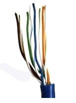
Carefully remove the outer jacket of the cable, exposing about 1 1/5 inch of the twisted pairs. Be careful when stripping the jacket as to not nick or cut the internal wiring. After removing the outer case, you will notice 8 wires twisted in 4 pairs. Each pair will have one wire of a certain color and another wire that is white with a colored stripe matching its partner (this wire is called a tracer). Sometimes a rip cord (white thread) is also present.
 Step 3:
Untwist the pairs so they will lay flat between your fingers. The white piece of thread can be cut off even with the jacket and disposed. For easier handling, cut the wires so that they are 3/4" (19 mm) long from the base of the jacket.
 Step 4:
Arrange the wires based on the wiring specifications you are following. There are two methods set by the TIA 568A and 568B. Which one you use will depend on what is being connected. A straight-through cable is used to connect two different-layer devices (e.g. a hub and a PC). Two like devices normally require a cross-over cable. The difference between the two is that a straight-through cable has both ends wired identically, while a cross-over cable has one end wired 568A and the other end wired 568B. For our demonstration in the following steps, we will use 568B, but the instructions can easily be adapted to 568A.
568B - Put the wires in the following order, from left to right:
White orange/ orange/ white green/ blue/ white blue/ green/ white brown/ brown
568A - Put the wires in the following order, from left to right:
White green/ green/ white orange/ blue/ white blue/ orange/ white brown/ brown
Step 5:
Press all the wires flat and parallel between your thumb and forefinger. Verify the colors have remained in the correct order. Cut the top of the wires even with one another so that they are 1/2" (12.5 mm) long from the base of the jacket, as the jacket needs to go into the 8P8C connector by about 1/8", meaning that you only have a 1/2" of room for the individual cables. Leaving more than 1/2" untwisted can jeopardize connectivity and quality. Ensure that the cut leaves the wires even and clean; failure to do so may cause the wire not to make contact inside the jack and could lead to wrongly guided cores inside the plug.
 Step 6:
Keep the wires flat and in order as you push them into the RJ-45 plug with the flat surface of the plug on top. The white/orange wire should be on the left if you're looking down at the jack. You can tell if all the wires made it into the jack and maintain their positions by looking head-on at the plug. You should be able to see a wire located in each hole, as seen at the bottom right. You may have to use a little effort to push the pairs firmly into the plug. The cabling jacket should also enter the rear of the jack about 1/4" (6 mm) to help secure the cable once the plug is crimped. You may need to stretch the sleeve to the proper length. Verify that the sequence is still correct before crimping.
Step 7:
Place the wired plug into the crimping tool. Give the handle a firm squeeze. You should hear a ratcheting noise as you continue. Once you have completed the crimp, the handle will reset to the open position. To ensure all pins are set, some prefer to double-crimp by repeating this step.
.jpg) Step 8:
Step 8:Repeat all of the above steps with the other end of the cable. The way you wire the other end (568A or 568B) will depend on whether you're making a straight-through, rollover, or cross-over cable. Test the cable to ensure that it will function in the field. In addition, with power-over-Ethernet (PoE) making its way into the market place, crossed wire pairs could lead to physical damage of computers or phone system equipment, making it even more crucial that the pairs are in the correct order. A simple cable tester can quickly verify that information for you. Should you not have a network cable tester on hand, simply test connectivity pin to pin.
See also Wiring Code for 10BaseT/ 100BaseT Cable


 This ensures effective cooling when there is another card in front blocking the fan inlet. By expelling the hot air, IceQ 4 removes all the heat generated by the GPU out of the computer chassis, prevents the hot air from accumulating inside and enhancing the overall stability and gives more 19% cooler than other cards. It has ATI Crossfire Advantage, the fan ensures effective cooling with another card blocking at front. Silent and durable fan significantly reduce noise level and extend service life. HIS by tooling up their IceQ4 Cooler not only made their card silent but were able to do that and make the card operate some 20 degrees cooler than others. Dual Heatpipe Heat is rapidly transferred from the core area reducing the GPU temperature. A dual-slot cooling design ensures you can conveniently connect the ATI Crossfire cable to run an ATI Crossfire setup. Other brands' cooler which is greater than Dual-slot cannot run CrossFire Setup in some motherboards. UV Sensitive IceQ4 will glow under UV light. As stated, the plastic cooler is UV reflective, throw in a 5 USD UV cold-cathode and you can get that nice dark ocean blue thing going on. The HIS HD 4850 IceQ 4 TurboX cooler is both silent and offers much better than reference cooling performance. Next to that, it looks quite nice as well, throw in a little cold-cathode UV light and the thing will shine up like it's radiated... lovely to look at it.
 As graphics cards go, the HIS HD 4850 IceQ 4 TurboX looks simply awesome. Using a cooler not dissimilar in appearance to the previous generation of Arctic Cooling's 'Silencer' series, a blower fan mounted at the rear of the card pushes air through copper coloured (but most likely aluminium) fins attached to a base plate. As mentioned previously, both the Memory and PLL heatsinks are isolated from the main GPU cooler which is probably a good thing considering how hot the 4800 series cores can get.
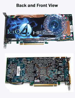
 At the front of the card you'll find the standard configuration of two DVI ports and an S-Video port bolted to the dual-slot blanking plate. However, HIS have seen fit to gold plate the connections on the DVI ports and also electroplate the blanking plate in a gunmetal black colour. This further improves the aesthetic appeal of the card, which combined with the custom blue PCB, makes it probably the best looking graphics card we've ever seen. The World's Fastest HD4850 - HIS HD4850 IceQ 4 TurboX HD 4850 IceQ 4 Turbo X posting significantly faster scores than the standard HD 4850 and the GeForce 9800 GTX+.
 Make no mistake, the